


Features
- Five Degrees of Freedom Plus Rotational Adjustment
- Low Hysteresis (See Graphs Tab for More Information)
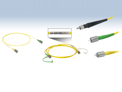
- FC/PC, FC/APC, and SMA Versions
- FC/PC and FC/APC Versions Accept Both 2.1 mm Wide Key and 2.0 mm Narrow Key Connectors
- SMA FiberPorts Are Designed for SMA905 Connectors
- Available with Either an Achromatic Doublet or an Aspheric Lens
- Suitable for Single Mode (SM), Multimode (MM), and Polarization-Maintaining (PM) Fiber
- AR Coating Options for Visible, NIR, and MIR Wavelength Ranges (See Selection Guide Tab for Details)
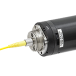
Thorlabs’ compact, ultrastable FiberPort micropositioners provide an easy-to-use platform for coupling light into and out of optical fibers. Their compact size; repeatable, high-resolution alignment mechanism; high thermal stability*; and translation locking mechanisms (detailed in the Operation tab) make these FiberPorts an ideal solution for long- or short-term fiber coupling and collimation. Each FiberPort is factory-aligned for collimation at the wavelength specified in its respective mechanical drawing. For information about the hysteresis and thermal stability, please see the Graphs tab.
Each FiberPort includes an achromatic doublet or aspheric lens with an effective focal length ranging from 2.0 mm to 18.4 mm. They are available with FC/PC, FC/APC, or SMA fiber bulkheads. For applications that are compatible with short effective focal lengths (≤7.5 mm), we offer FiberPorts with FC bulkheads that can be used with both FC/PC and FC/APC connectors. Their 5-axis adjustment combined with their short focal length leads to negligible off-axis sensitivity. For more details on how to select a FiberPort, please see the Selection Guide tab.
For a higher maximum theoretical coupling efficiency, we recommend using FiberPorts with our AR-coated single mode, multimode, or polarization-maintaining fiber optic patch cables for coupling and collimating light, as these patch cables reduce back reflections from high powered sources. For FiberPorts being used in the mid-infrared spectral region, we recommend our fluoride fiber patch cables.
Achromatic FiberPorts
Our achromatic FiberPorts collimate light over a large wavelength range with a very small focal length shift. This reduces the need for realignment if the wavelength of the source is changed. The focal length shift for both the achromatic and similar aspheric FiberPorts can be seen in the Selection Guide tab above. These FiberPorts are available with an effective focal length of 4.0 mm, 7.5 mm, 10 mm, or 15 mm. The EFL shift for each achromatic FiberPort can be viewed in the tables below.
Five Degrees of Freedom (Plus Bulkhead Rotation)
While holding the connector and fiber stationary, the built-in lens can be aligned with five degrees of freedom: linear alignment of the lens in X and Y, angular alignment for tip and tilt, and Z adjustment using the tip and tilt controls simultaneously. The travel range of the aspheric lens in the X and Y direction is ±0.7 mm with a resolution of 317 µm per revolution. The travel range in the Z direction is ±1.0 mm with resolution of 200 µm per revolution. In addition, the three flat-head screws on the front plate can be loosened to enable rotation of the bulkhead for PM fiber alignment. After alignment is complete, a locking setscrew on the side of the housing can be tightened to secure the X and Y position, as can the locking collars on the Zθ adjusters to lock the tip/tilt position. See the Operation tab for complete details on operating a FiberPort.
Mounting Options
FiberPorts contain four #2 counterbores that provide mechanical compatibility with our FiberBench accessories. We have also developed adapters for using FiberPorts with Ø1/2″ posts, 30 mm cage systems, and HeNe lasers. Please see the FiberPort Mounts tab for more information.
Included Hardware
These FiberPorts include a dust cap, a 0-80 locking screw, a 0.028″ hex key for the locking screw, a 0.050″ hex key for the Zθ, X, and Y adjusters, and an SPW403 spanner wrench for the Zθ locking collars.
*Please note the maximum recommended temperature for operation is 80 °C.
Additional information
 |
 |
 |
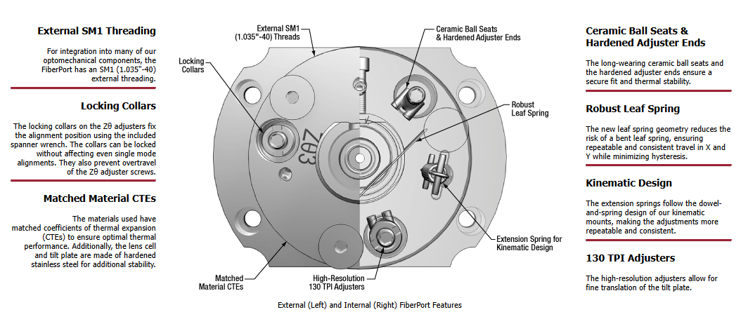
| Internal Mechanism of the FiberPort With and Without the Outer Body Removed |
Zθ Adjustment |
X-Y Adjustment |
|||||||||||||||||||||||
|
 |
|
 |
|||||||||||||||||||||
| Each FiberPort consists of a lens cell that is magnetically adhered to a tilt plate. This tilt plate is actuated using three Zθ adjusters, highlighted in green above. Each adjuster is labeled with Zθ1, Zθ2, or Zθ3 so it is easy to tell which adjuster has been or will be adjusted. Turning each adjuster in equal increments enables Z-translation along the optical axis of the FiberPort. The Z-axis translation range is ±1.0 mm. See the above table for additional specifications for our Zθ adjuster screws.
Once final adjustments are made, the position of the tilt plate can be locked via the included locking collars and SPW403 spanner wrench. These adjusters are lockable while maintaining single mode alignment. The mechanics behind translation of the tilt plate is very similar to the dowel-and-spring construction of our kinematic mounts. Each adjuster has a hardened steel ball-end that rides in a ceramic ball seat. Both the ball-end and ceramic seat are attached using a high temperature, low outgassing epoxy to provide a stable, long wearing kinematic system. The extension springs provide counterforce against the fine adjust screws. |
The magnetic lens cell (MLC) can be translated in X-Y, independently from the tilt plate, using the socket head cap screws (SHCS) in the side of the FiberPort body, highlighted in red and blue above. Each adjuster is labeled as X and Y for easy and quick identification. The travel range of the lens in the X and Y directions is ±0.7 mm. See the above table for additional specifications for our X-Y adjuster screws. Note that when a FiberPort is used in a standard collimation or coupling application, only a small portion of this translation range is needed.
X-Y translation is performed independently from angular and Z-axis adjustments. The lens cell, which is magnetically attached to the tilt plate, rests on a leaf spring that provides a counterforce. The resistance of the adjustments made with these screws can be changed using the X-Y tension adjusters discussed below; each adjuster has been highlighted with the same color as its tension adjuster here. The X-Y motion can be locked in place using the locking screw discussed below. |
|||||||||||||||||||||||
X-Y Tension |
X-Y Lock |
|||||||||||||||||||||||
|
 |
|
 |
|||||||||||||||||||||
| Each X-Y adjuster can have its tension adjusted using the corresponding tension screws on the face of the FiberPort. By tightening the tension of an adjuster, it is easier to make small adjustments to the MLC without overshooting the desired position. Conversely, loosening the tensions makes it easier to make large adjustments without applying excessive force. | A setscrew on the bottom of the Fiberport can be used to retain the position of the X and Y adjustment screws. Most applications do not require locking the FiberPort. For example, if the FiberPort is in a low-vibration environment than the locking screw does not need to be engaged. However, for situations where the FiberPort might undergo large vibrations or shock, such as shipping, the setscrew should be engaged. Using the locking screw can affect coupling; follow all applicable directions in the FiberPort manual when using the locking feature. Note that this locking screw is included but not installed when the FiberPort is shipped. | |||||||||||||||||||||||
 |
| The L in the above mechanical drawing calls out the overall length from the front of the FiberPort, minus the connector bulkhead, to the front face of the mounting flange. This value depends on the focal length and the connector bulkhead. See the tables below for the exact length of each FiberPort. |
AR Coatings |
 |
| Each FiberPort lens is available with -A (350 – 700 nm or 400 – 700 nm), -B (600 – 1050 nm or 650 – 1050 nm), -C (1050 – 1620 nm or 1050 – 1700 nm), -D (1.8 – 2.4 µm), or -E (2.0 – 5.0 µm) coating. Please refer to the tables below for the specific wavelength range of each FiberPort lens. |
Thermal Stability |
|
| Procedure: The thermal stability of the FiberPort was measured by changing the temperature of the environment by ±10 °C, and measuring the coupling efficiency as it varied with the temperature. These measurements were taken using a PAF2P-11A and PAF2P-11A on an FB-38 FiberBench. A 635 nm source was used with single mode fiber. Please note that the thermal stability depends highly on the components and system setup.Results: The ~5% change in coupling efficiency is a result of the movement of all components in this FiberBench/FiberPort system. This change results in approximately 0.5 µm movement of the beam spot relative to the fiber core. After the temperature has changed, upon returning to the original temperature, the coupling efficiency returns to within 1% of the original value. |
 |
Fine Axis Repeatability |
|
| Procedure: The repeatability of the Zθ adjustments was measured by translating the Zθ adjusters by 200-300 µrad and returning to the starting position at approximately (0,0). This was done three times. To measure this movement, a beam emitted from the FiberPort was transmitted to a CCD beam profiler. These measurements were done with the PAF2P-11A with an input wavelength of 635 nm.Results: As seen in the graph to the right, these FiberPorts exhibit good repeatability and low hysteresis. These values are typical and will change based on the selected wavelength and focal length of the FiberPort. |
 |
Introduction
Before selecting a FiberPort, it is crucial to consider:
- The wavelength of your source,
- The fiber type (single mode, multimode, or polarization maintaining),
- The fiber connector (FC/PC, FC/APC, or SMA), and
- The desired lens type (achromatic or aspheric).
With this information, it is possible to find what FiberPort is most compatible with your configuration. The method below illustrates the best way to find a FiberPort to use for coupling. This example considers a single mode fiber as the fiber that is being coupled. The calculations needed to determine whether a FiberPort is compatible with a single mode fiber are more complex than with a multimode fiber, which primarily considers the NA of the fiber and the lens.
Click the button to the right to download a macro-enabled Excel file that can assist in finding the best FiberPort for your coupling application. For additional questions, please contact Tech Support.
Calculating the Effective Focal Length
Example:
- Wavelength: 633 nm
- Fiber: P1-630A-FC-2
- Collimated Beam Diameter Prior to Lens: Ø3 mm
The specifications for the P1-630A-FC-2, 633 nm, FC/PC single mode patch cable indicate that the 1/e2 mode field diameter (MFD) is 4.3 μm at 633 nm. The MFD should equal the diffraction-limited spot size Øspot, which is given by the following equation:
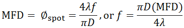
Here, f is the focal length of the lens, λ is the wavelength of the input light, and D is the 1/e2 diameter of collimated beam incident on the lens. Solving for the desired focal length of the collimating lens yields:
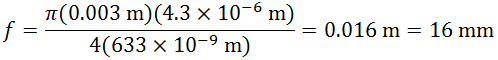
Thorlabs offers a large selection of FiberPorts. You’ll note that the FiberPort with a focal length closest to 16 mm has a focal length of 15.3 mm (Item # PAF2P-15A), while also meeting the requirements for fiber connector type and antireflection coating range. This FiberPort also has a clear aperture that is larger than the collimated beam diameter. Therefore, this is the best option given the initial parameters (i.e., a P1-630A-FC-2 single mode fiber and a collimated beam diameter of 3 mm).
For optimum coupling, the spot size of the focused beam must be less than the MFD of the single mode fiber. As a result, if a FiberPort is not available that provides an exact match, then choose the FiberPort with a focal length that is shorter than the calculation above yields. Alternatively, if the clear aperture of the lens is large enough, the beam can be expanded before the lens, which has the result of reducing the spot size of the focused beam.
Please note that the NA values in the specification tables below are the numerical apertures of the lenses, not the required numerical aperture of the fiber you are using. As long as the lens NA is smaller than the NA of your fiber, you should be able to couple light. Please note that if your collimated beam diameter is smaller than the clear aperture of the lens you will need to recalculate the NA using the beam diameter. For best results, Thorlabs recommends using the equations above when choosing a FiberPort, or to use the calculator linked above.
Selecting a Lens
When selecting a FiberPort, it is essential to ensure that the lens included in the FiberPort is compatible with your setup. In particular, the wavelength of the laser source must fall within the AR coating range of the lens, and the spot radius and focal shift should perform in such a way that is beneficial to your system.
AR CoatingsThe lenses in Thorlabs’ FiberPorts use our -A (350 – 700 nm or 400 – 700 nm), -B (600 – 1050 nm or 650 – 1050 nm), -C (1050 – 1620 nm or 1050 – 1700 nm), -D (1800 – 2400 nm), or -E (2000 – 5000 nm) AR coatings. The plot to the right shows the typical per-surface reflectance of each AR coating. Each AR-coated lens is housed in a FiberPort package designed to be compatible with FC/PC-, FC/APC-, or SMA-terminated fibers. Care should be taken in selecting a FiberPort to make sure the correct fiber/connector/FiberPort combination is selected. AR-coating information and connector compatibility for each FiberPort are outlined in the tables below. Contact Tech Support for assistance. Note: The C coating wavelength range specification was recently updated from 1050 – 1620 nm to 1050 – 1700 nm. All optics in stock currently have a C coating with a wavelength range of 1050 – 1700 nm. However, we are in the process of updating our documentation, and so some individual optics may still be presented with the old wavelength range on our website. |
 |
Aspheric vs. Achromatic FiberPort Performance
Thorlabs’ achromatic FiberPorts utilize cemented doublets designed to minimize chromatic aberrations, making them ideal for collimating broadband light sources or sources with multiple discrete wavelengths. The small focal length shifts experienced by an achromatic doublet allow the FiberPort to be used over a broad wavelength range without the need for realignment (see the Graphs tab for more details).
 |
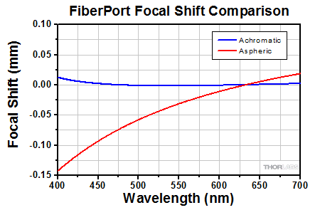 |
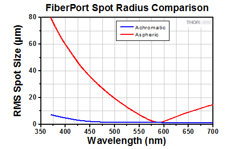
| The performance of the achromatic doublet used in an achromatic FiberPort is compared to the aspheric lens used in a FiberPort with the same effective focal length, for a collimated beam focused onto a fiber. The lens is aligned to focus the light onto the fiber at 580 nm. Over a given wavelength range, the achromatic doublet produces a focused spot on the fiber, while the aspheric lens produces a series of wavelength dependent foci along its optical axis due to chromatic focal shift. Since the fiber’s position was fixed at the focus of the aspheric lens, the spot size changed drastically with wavelength. However, appropriate adjustment of the fiber’s position as the wavelength is changed can minimize this effect. | This graph represents the focal length shift for the same setup described in the plot to the left. Both lenses have a similar focal length (F) at ~580 nm. Overall, the focal shift experienced by the aspheric lens in the range 475 nm – 655 nm (except ~580 nm) is approximately an order of magnitude larger than that of the achromatic doublet. For wavelengths less than 580 nm, the beam comes to a focus at a distance < F and longer wavelengths are focused at a distance > F. |
| FiberPort Cage Mount | FiberPort Post Mount | ||
 |
The CP08FP FiberPort Cage Mount is designed to center a FiberPort inside a 30 mm cage system. The CP08FP secures to the four ER rods of a 30 mm cage assembly. Four included 2-56 stainless steel socket head screws secure a FiberPort to the adapter. The CP08FP has internal SM1 (1.035″-40) threading, enabling it to be used with our extensive line of Ø1″ lens tubes, and also 8-32 or M4 taps for post mounting. |  |
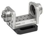
The HCP Post Mounting Bracket has four 2-56 threaded holes for securing a FiberPort to the front plate. The bottom of the L-bracket can be easily attached to an optical table, breadboard, or post, since it has 8-32- and M4-threaded holes, as well as a 1/4″ (M6) counterbored hole. |
| FiberPort Standard HeNe Adapter | FiberPort 5/8″-32 Threaded HeNe Adapter | ||
 |
The HCL HeNe to FiberPort Adapter attaches a FiberPort directly to the front of a HeNe laser with an industry-standard four-bolt pattern. For additional mounting options, the HCL features internal C-Mount (1.000″-32) threading, which is utilized on some lasers. All mounting screws are included. |  |
The HCL2 Self-Contained HeNe to FiberPort Adapter, which features external 5/8″-32 threading, allows a FiberPort coupler to be attached directly to the threaded aperture of our self-contained HeNe lasers or any other 5/8″-32 tapped hole. A slip-plate design allows the position of the FiberPort to be shifted and locked to maximize coupling efficiency. FiberPort mounting screws are included. |
 |
Thorlabs’ fiber-to-fiber U-Benches consist of a FiberBench base combined with two FiberPorts. The U-Benches allow for easy access to the optical beam and are ideal for fiber-to-fiber applications that incorporate multiple components and require the utmost in stability. Thorlabs offers a complete line of optical subassemblies that can be placed into the beam path. We also offer our FiberBenches bundled with two compatible FiberPorts. | ||