Features
- High Switching Speed of 1 ns (Typ.)
- 1550 nm Wavelength Operation
- Polarization-Dependent and Independent Versions
- Fiber Pigtails with FC/APC Connectors
- Case Temperature Control via Internal Thermoelectric Cooler (TEC) Element
Thorlabs’ High-Speed Optical Shutters/Switches are designed specifically for applications requiring an optical shutter with operation around 1550 nm. All our optical switches provide an extinction ratio greater than 60 dB. The devices are based on our semiconductor amplifier platform consisting of a highly efficient InP/InGaAsP Multiple Quantum Well (MQW) layer structures grown on an InP wafer and processed into a proven and reliable ridge waveguide. The device can operate as a lossless, high-speed, optical isolation switch, a full-range variable optical attenuator (VOA), or an optical shutter for protection of delicate optical equipment.
Mount and Driver Options
These butterfly packages are compatible with the CLD1015 laser diode mount with integrated controller and TEC, however, this controller will only be able to achieve switching speeds of around 4 µs. They are also compatible with the LM14TS and LM14S2 mounts, which can be used with our laser diode, TEC, and combined current/TEC controllers. When operating these lasers in environments with more than 5 °C variation in temperature, we recommend using the LM14TS mount, which provides active control of the butterfly package’s case temperature to stabilize the amplifier’s output wavelength and power. For information on compatible drivers that can achieve switching times up to the specified 1 ns time scale, please contact USContact Us
Polarization-Dependent Optical Shutters/Switches
| Item # |
BOA1004PXS |
BOA1550PXSa |
| Parameter |
Min |
Typical |
Max |
Min |
Typical |
Max |
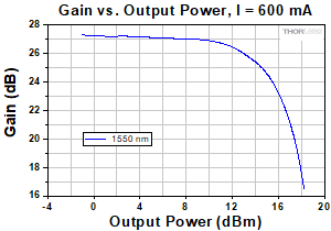
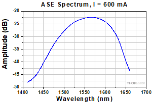
| Operating Current (IOP) |
– |
600 mA |
750 mA |
– |
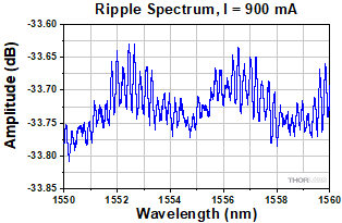
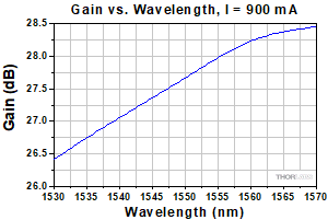
900 mA |
950 mA |
| Operating Wavelength |
1500 nm |
– |
1600 nm |
– |
– |
– |
| ASE Center Wavelength |
– |
– |
– |
1530 nm |
1550 nm |
1580 nm |
| Optical 3 dB Bandwidth |
– |
– |
– |
95 nm |
105 nm |
– |
| Optical Isolation (PIN/POUT) @ 0 mA and 1550 nm |
40 dB |
– |
– |
40 dB |
– |
– |
| Extinction Ratio (On/Off @ PIN = -20 dBm and 1550 nm) |
– |
70 dB |
– |
– |
70 dBb |
– |
| Switching Speed |
– |
1 ns |
– |
– |
1 ns |
– |
| Max Output Power for CW Input Signal |
– |
18 dBm |
– |
– |
21 dBmc |
– |
| Max Output Power for Modulated Input Signal |
– |
10 dBm |
– |
– |
See Footnote d |
– |
| Saturation Output Power (@ -3 dB) |
13 dBm |
15 dBm |
– |
17 dBmb,c |
18 dBmb,c |
– |
| Noise Figure |
– |
8.0 dB |
9.5 dB |
– |
8.5 dBb,c |
9.5 dBb,c |
| Small Signal Gain (@ PIN = -20 dBm) |
22 dBe |
25 dBe |
– |
24 dBb,c |
27 dBb,c |
– |
| Forward Voltage |
– |
1.6 V |
1.8 V |
– |
1.6 Vb |
2.1 Vb |
| Chip Length |
– |
1.5 mm |
– |
– |
1.5 mm |
– |
| Waveguide Refractive Index |
– |
3.2 |
– |
– |
3.2 |
– |
| Thermoelectric Cooler (TEC) Operation (Typical/Max @ TCASE = 25 °C/70 °C) |
| TEC Current |
– |
0.23 A |
1.5 A |
– |
0.55 A |
1.5 A |
| TEC Voltage |
– |
0.5 V |
4 V |
– |
0.70 V |
4.0 V |
| Thermistor Resistancef |
– |
10 kΩ |
– |
– |
10 kΩ |
– |
| Absolute Maximum Ratingsg |
| Operating Current |
– |
– |
– |
– |
– |
950 mA |
| Optical Output Power, CW |
– |
– |
– |
– |
– |
150 mW |
| Chip Temperature (TEC) |
– |
– |
– |
10 °C |
– |
30 °C |
| Case Temperature |
– |
– |
– |
0 °C |
– |
70 °C |
| Fiber Specifications |
| Type (PM Fiber) |
Corning PMF-1550 |
Corning PM15-U40A |
| Mode Field Diameter |
– |
10.5 ± 0.5 µm @ 1550 nm |
| Numerical Aperture |
– |
0.125 |
| Length |
1.5 ± 0.1 m |
1.5 m |
| Connector |
FC/APC, Key Aligned to Slow Axis |
Polarization-Independent Optical Shutter/Switch
| Item |
SOA1013SXS |
| Parameter |
Min |
Typical |
Max |
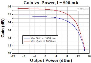
| Operating Current |
– |
500 mA |
600 mA |
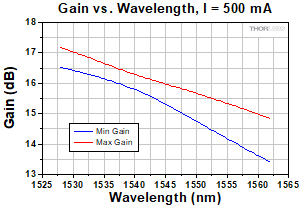
| Operating Wavelength |
1528 nm |
– |
1562 nm |
| Optical Isolation (PIN/POUT) @ 0 mA and 1550 nm |
42 dB |
– |
– |
| Extinction Ratio (On/Off @ PIN = -20 dBm and 1550 nm) |
– |
60 dB |
– |
| Switching Speed |
– |
1 ns |
– |
| Max Output Power for CW Input Signal |
– |
17 dBm |
– |
| Max Output Power for Modulated Input Signal |
– |
9 dBm |
– |
| Saturation Output Power (@ -3 dB) |
12 dBm |
14 dBm |
– |
| Noise Figure |
– |
8.0 dB |
9.5 dB |
| Small Signal Gain Across Bandwidth (@ PIN = -20 dBm) |
10 dB |
13 dB |
– |
| Polarization Dependent Gain |
– |
1 dB |
1.8 dB |
| Forward Voltage |
– |
1.6 V |
1.8 V |
| Chip Length |
– |
1.5 mm |
– |
| Waveguide Refractive Index |
– |
3.2 |
– |
| Thermoelectric Cooler (TEC) Operation (Typical/Max @ TCASE = 25 °C/70 °C) |
| TEC Current |
– |
0.23 A |
1.5 A |
| TEC Voltage |
– |
0.5 V |
4 V |
| Thermistor Resistancea |
– |
10 kΩ |
– |
| Fiber Specifications |
| Type (SM Fiber) |
SMF-28-J9 |
| Length |
1.5 ± 0.1 m |
| Connector |
FC/APC |
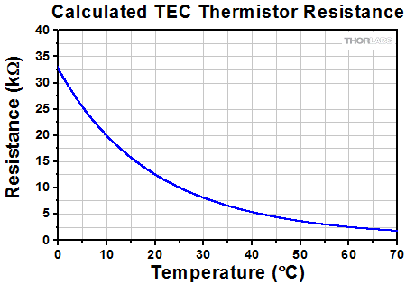 |
| Figure 2.1 Calculated Thermistor Resistance |
This is plotted using the Steinhart-Hart equation,
where A = 1.129241 x 10⁻³, B = 2.341077 x 10⁻⁴, and C = 8.775468 x 10⁻⁸.