


- Piezo Inertia, DC Servo, or Stepper Actuators with 25 mm of Travel
- Load Capacities Up to 55 lbs (25 kg) Available
- Maximum Speeds Up to 50 mm/s Available
- Compatible with a Wide Range of Stages
Features
- 1″ (25 mm) Travel
- Stepper Motor, Servo Motor, and Piezo Inertia Actuator Models
- Rotating and Non-Rotating Drive Tips
- Replace Micrometers on Manual Stages and Mounts
Thorlabs’ Motorized Actuators are designed for use with optical positioning devices. They offer high resolution in lightweight packages, which makes these actuators ideally suited for demanding optical automation applications. These 1″ (25 mm) travel motorized actuators are available with three drive types: 2-phase stepper motors, DC servos with encoders, or piezo inertia actuators. Vacuum-compatible models with DC servos or piezo inertia actuators provide functionality down to 10-6 Torr. See the table to the right for an overview of the available models or below for more details.
| Item # | ZFS25B | ZST225B | DRV225 | Z925B | Z925BV | PIA25 | PIA25VF |
|---|---|---|---|---|---|---|---|
| Travel | 25 mm (0.98″) | ||||||
| Motor Type | 2-Phase Stepper | DC Servo w/ Encoder |
Piezo Inertia Acuator | ||||
| Mounting | Ø3/8″ (Ø9.525 mm) Barrel | Two M4 Cap Screws | Ø3/8″ (Ø9.525 mm) Barrel | ||||
| Vacuum Rating | N/A | N/A | 10-6 Torr | N/A | 10-6 Torr | ||
| Required Controller | KST201 | BSC201, BSC202, BSC203, or MST602 |
KDC101 | KIM001 or | |||
Accordion title
ZFS25B and ZST225B Actuators
| Pin Diagram
|
15-Pin D-Sub Connector Pin Out |
|||||||||||||||||||||||||||||||||||
|
DRV225 Actuator
| Pin Diagram
|
15-Pin D-Sub Connector Pin Out |
|||||||||||||||||||||||||||||||||||
|
Z925B Actuator
| Pin Diagram
|
15-Pin D-Sub Connector Pin Out |
|||||||||||||||||||||||||||||||||
|
Z925BV Actuator
The vacuum-compatible cable integrated with the Z925BV actuator is terminated in a female IDC 10-Pin socket connector. A short converter cable, which adapts this female IDC socket connector to a D-type male HD15 pin connector, is included with the Z925BV actuator to facilitate connecting it to the recommended KDC101 controller. This converter cable, whose terminating connectors are shown below, is not vacuum compatible. Information describing the pin assignments for both the female IDC socket and male D-type HD connector (when it is connected to the female IDC socket connector) follows.
|
Pin Diagram 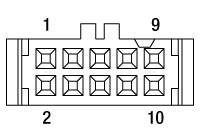 10 Pin Female IDC Socket Connector (Amphenol T812 Series, 2.54 mm Pitch) |
Female IDC 10-Pin Connector Pin Out |
(Amphenol T812 Series, 2.54 mm Pitch) |
||||||||||||||||||||||||||||||
|
||||||||||||||||||||||||||||||||
Pin Diagram
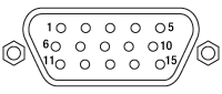 High-Density D-Type Male 15 Pin Connector |
Male HDDB15 Connector Pin Out |
|||||||||||||||||||||||||||||||
|