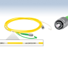


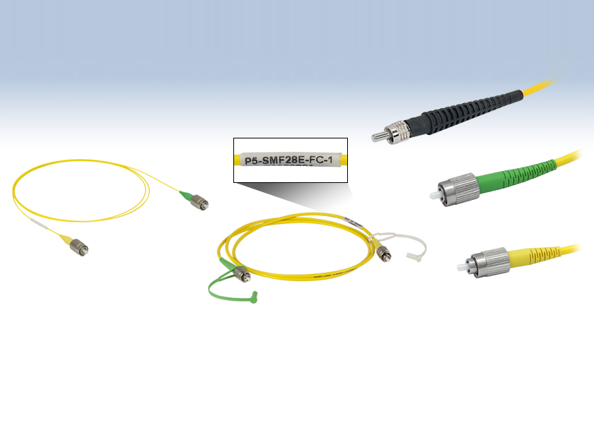
These cables are available with either 0.9 mm yellow Hytrel or 0.3 mm yellow PVC jackets, and they come with protective caps to prevent dust and damage to the fiber ends. Additional accessories such as end caps and mating sleeves are also available. Thorlabs also offers custom cable lengths and configurations to meet specific application requirements.
Features:
- Single Mode Fiber Optic Adapter Cables for 305 nm to 2200 nm transmission
- FC/PC to FC/APC or FC/PC to SMA Connector Options
- Narrow Key FC/PC and FC/APC Connectors
- 0.900 µm or 0.3 mm Jackets
- Custom Cables Offered
ThorLabs Single Mode Hybrid Fiber Optic Patch Cables
Fiber: SM300, SM400, S405-XP
| Item # Prefix | P5-305A-PCAPC | P5-405B-PCAPC | P2-405B-PCSMA | P5-S405Y-FC | P5-S405-FC |
|---|---|---|---|---|---|
| Fiber | SM300 | SM400 | S405-XP | ||
| Operating Wavelength | 320 – 430 nm | 405 – 532 nm | 400 – 680 nm | ||
| Cutoff Wavelength | ≤310 nm | 305 – 400 nm | 380 ± 20 nm | ||
| Mode Field Diameter (MFD)b | 2.0 – 2.4 µm @ 350 nm | 2.5 – 3.4 µm @ 480 nm | 3.3 ± 0.5 µm @ 405 nm 4.6 ± 0.5 µm @ 630 nm |
||
| Cladding Diameter | 125 ± 1.0 µm | 125 ± 1.0 µm | 125 ± 1.0 µm | ||
| Coating Diameter | 245 ± 15 µm | 245 ± 15 µm | 245 ± 15 µm | ||
| Attenuation (Max)c | ≤70 dB/km @ 350 nm | ≤50 dB/km @ 430 nm ≤30 dB/km @ 532 nm |
≤30.0 dB/km @ 630 nm ≤30.0 dB/km @ 488 nm |
||
| NA | 0.12 – 0.14 | 0.12 – 0.14 | 0.12 | ||
| Return Losse | FC/PC Connectors: 50 dB Typical (40 dB Min) FC/APC Connectors: 60 dB Typical |
||||
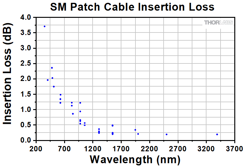
| Typical Insertion Lossf (Click to Enlarge) (FC/PC and FC/APC Connectors)g |
 |
||||
| Connectorsh | FC/PC to FC/APC (30126C3 to 30126A3) |
FC/PC to FC/APC (30126C3 to 30126A3) |
FC/PC to SMA (30126C3 to 10125A) |
FC/PC to FC/APC (30126C3 to 30126A3) |
|
| Length | 1 m | ||||
| Furcation Tubing | Ø3 mm Yellow PVC | Ø900 µm Hytrel®i | Ø3 mm Yellow PVC | ||
Fiber: SM450, S630-HP, SM600
| Item # Prefix | P5-460B-PCAPC | P2-460B-PCSMA | P5-S630Y-FC | P5-S630-FC | P5-630Y-FC | P5-630A-PCAPC | P2-630A-PCSMA |
|---|---|---|---|---|---|---|---|
| Fiber | SM450 | S630-HP | SM600 | ||||
| Operating Wavelength | 488 – 633 nma | 630 – 860 nm | 633 – 780 nm | ||||
| Cutoff Wavelength | 350 – 470 nma | 590 ± 30 nm | 500 – 600 nm | ||||
| Mode Field Diameter (MFD)a | 2.8 – 4.1 µm @ 488 nm | 4.2 ± 0.5 µm @ 630 nm | 3.6 – 5.3 µm @ 633 nm | ||||
| Cladding Diameter | 125 ± 1.0 µm | 125 ± 1.0 µm | 125 ± 1.0 µm | ||||
| Coating Diameter | 245 ± 15 µm | 245 ± 15 µm | 245 ± 15 µm | ||||
| Attenuation (Max)b | ≤50 dB/km @ 488 nmd | ≤10 dB/km @ 630 nm | ≤15 dB/kmc | ||||
| NA | 0.10 – 0.14 | 0.12 | 0.10 – 0.14 | ||||
| Return Lossd | FC/PC Connectors: 50 dB Typical (40 dB Min)FC/APC Connectors: 60 dB Typical | ||||||
| Typical Insertion Losse (Click to Enlarge) (FC/PC and FC/APC Connectors)f |
 |
||||||
| Connectorsg | FC/PC to FC/APC (30126C3 to 30126A3) |
FC/PC to SMA (30126C3 to 10125A) |
FC/PC to FC/APC (30126C9 to 30126A9) |
FC/PC to FC/APC (30126C9 to 30126A9) |
FC/PC to FC/APC (30126C3 to 30126A3) |
FC/PC to SMA (30126C3 to 10125A) |
|
| Length | 1 m | ||||||
| Furcation Tubing | Ø3 mm Yellow PVC | Ø900 µm Hytrel®h | Ø3 mm Yellow PVC | Ø900 µm Hytrel®h | Ø3 mm Yellow PVC | ||
Fiber: 780HP, SM800-5.6-125
| Item # Prefix | P5-780Y-FC | P5-780A-FC P5-780A-PCAPC |
P2-780A-PCSMA | P5-830A-PCAPC | P2-830A-PCSMA |
|---|---|---|---|---|---|
| Fiber | 780HP | SM800-5.6-125 | |||
| Operating Wavelength | 780 – 970 nm | 830 – 980 nm | |||
| Cutoff Wavelength | 730 ± 30 nm | 660 – 800 nm | |||
| Mode Field Diameter (MFD)a | 5.0 ± 0.5 µm @ 850 nm | 4.7 – 6.9 µm @ 830 nm | |||
| Cladding Diameter | 125 ± 1 µm | 125 ± 1.0 µm | |||
| Coating Diameter | 245 ± 15 µm | 245 ± 15 µm | |||
| Attenuation (Max)b | ≤4.0 dB/km @ 780 nm ≤3.5 dB/km @ 850 nm |
<5 dB/kmc | |||
| NA | 0.13 | 0.10 – 0.14 | |||
| Return Lossd | FC/PC Connectors: 50 dB Typical (40 dB Min) FC/APC Connectors: 60 dB Typical |
FC/PC Connectors: 50 dB FC/APC Connectors: 60 dB |
|||
| Typical Insertion Losse (Click to Enlarge) (FC/PC and FC/APC Connectors)f |
 |
||||
| Connectorsg | FC/PC to FC/APC (30126C9 to 30126A9) |
FC/PC to FC/APC (30126C3 to 30126A3) |
FC/PC to SMA (30126C3 to 10125A) |
FC/PC to FC/APC (30126C3 to 30126A3) |
FC/PC to SMA (30126C3 to 10125A) |
| Length | 1 m (Items Ending in -1) 2 m (Items Ending in -2) |
1 m (Items Ending in -1) 2 m (Items Ending in -2) 5 m (Items Ending in -5) 10 m (Items Ending in -10) |
1 m | 1 m | |
| Furcation Tubing | Ø900 µm Hytrel®h | Ø3 mm Yellow PVC | Ø3 mm Yellow PVC | ||
Fiber SM980-5.8-125, HI1060-J9, SMF-28 Ultra
| Item # Prefix | P5-980A-PCAPC | P2-980A-PCSMA | P5-1064Y-FC | P5-SMF28Y-FC | P5-SMF28E-FC | P2-SMF28-PCSMA |
|---|---|---|---|---|---|---|
| Fiber | SM980-5.8-125 | HI1060-J9 | SMF-28 Ultra | |||
| Operating Wavelength | 980 – 1550 nm | 980 – 1650 nm | 1260 – 1625 nm | |||
| Cutoff Wavelength | 870 – 970 nm | 920 ± 50 nm | <1260 nm | |||
| Mode Field Diameter (MFD)a | 5.3 – 6.4 µm @ 980 nm | 5.9 ± 9.3 µm @ 980 nm 6.2 ± 0.3 µm @ 1060 nm |
9.2 ± 0.4 µm @ 1310 nm 10.4 ± 0.5 µm @ 1550 nm |
|||
| Cladding Diameter | 125 ± 1.0 µm | 125 ± 0.5 µm | 125 ± 0.7 µm | |||
| Coating Diameter | 245 ± 15 µm | 245 ± 10 µm | 242 ± 5 µm | |||
| Attenuationb | ≤2.0 dB/kmc | 2.1 dB/km @ 980 nm 1.5 dB/km @1060 nm |
≤0.32 dB/km @ 1310 nm (Max) ≤0.18 dB/km @ 1550 nm (Max) |
|||
| NA | 0.13 – 0.15 | 0.14 | 0.14 | |||
| Return Lossc | FC/PC Connectors: 50 dBFC/APC Connectors: 60 dB | |||||
| Typical Insertion Lossd (Click to Enlarge) (FC/PC and FC/APC Connectors)e |
 |
|||||
| Connectorsf | FC/PC to FC/APC (30126C3 to 30126A3) |
FC/PC to SMA (30126C3 to 10125A) |
FC/PC to FC/APC (30126C9 to 30126A9) |
FC/PC to FC/APC (30126C9 to 30126A9) |
FC/PC to FC/APC (30126C3 to 30126A3) |
FC/PC to SMA (30126C3 to 10125A) |
| Length | 1 m | 1 m (Items Ending in -1) 2 m (Items Ending in -2) 5 m (Items Ending in -5) |
1 m | |||
| Furcation Tubing | Ø3 mm Yellow PVC | Ø900 µm Yellow Hytrel®g | Ø3 mm Yellow PVC | |||
Fiber: SM1950
| Item # Prefix | P5-1950-PCAPC | P2-1950-PCSMA |
|---|---|---|
| Fiber | SM1950 | |
| Operating Wavelength | 1850 – 2200 nm | |
| Cutoff Wavelength | 1720 nm ± 80 nm | |
| Mode Field Diameter (MFD)a | 8.0 µm @ 1950 nm | |
| Cladding Diameter | 125 ± 1 µm | |
| Coating Diameter | 245 ± 10 µm | |
| Attenuationb | 5 dB/km @1900 nm (Typical) | |
| NA | 0.20 | |
| Return Lossc | FC/PC Connectors: 50 dBFC/APC Connectors: 60 dB | |
| Typical Insertion Lossd (Click to Enlarge) (FC/PC and FC/APC Connectors)e |
 |
|
| Connectorsf | FC/PC to FC/APC (30126C3 t1 m 30126A3) |
FC/PC to SMA (30126C3 to 10125A) |
| Length | ||
| Furcation Tubing | Ø3 mm Yellow PVC | |